Traditional timber framed buildings in Suffolk invariably have pitched roof structures, originally covered either with thatch, clay tiles, or later with slates imported from other parts of the country. These coverings are supported by timber rafters, regularly spaced timber members running up and down the roof, which are then in turn themselves supported by a variety of means.
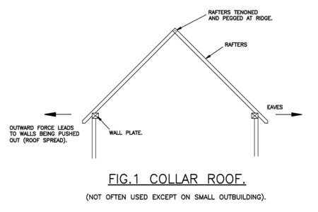
When a building has a duo pitched roof, pairs of rafters are in effect propped against each other and traditionally were often tenoned and pegged together at the ridge or apex (Fig. 1). Because in this arrangement the rafters lean against each other, they exert an outward force at their feet (eaves level) and will tend to push apart the walls they are built off. This is referred to as roof spread.
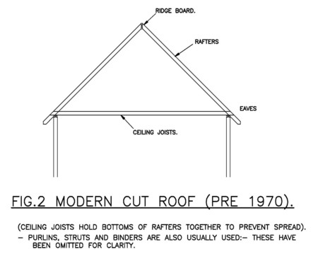
n modern cut timber roofs (pre 1970) constructed on site this force is normally resisted by joining the bottom of each pair of rafters (see Fig. 2) with ceiling joists. This ties them together and prevents any outward movement. It also leaves a void (the loft) which can be used for storage or the placing of water tanks etc.
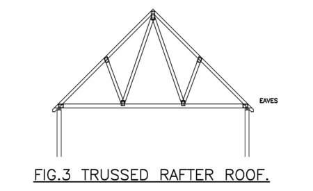
Alternatively on buildings later than 1970 the rafters, ceiling joists and internal bracing can be fabricated off site as what are called trussed rafters (Fig. 3).
However, in some instances there is a requirement to use the loft void as living space and produce a vaulted roof structure and in this case the rafters can be supported at the apex by a ridge beam usually in steel, solid timber or laminated timber spanning between cross walls or posts (see Fig. 4). As long as the beam is stiff enough and is adequately supported at its ends it effectively holds the rafters up in the middle and prevents them spreading outwards at their lower ends.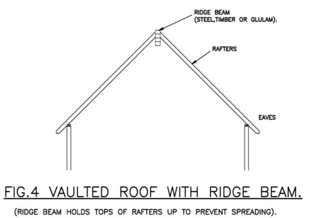
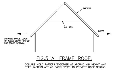
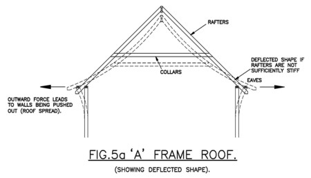
A further variation on this is the A frame roof (see Fig. 5) where regular timber members (called collars) are provided further up the rafters than at eaves level. This allows the use of some of the space within the roof as living space giving a room shape with more character and effectively reducing the height of the roof and thus the ‘bulk’ of the building. With this arrangement the rafters are tied together at collar level but tend to spread below this level (see Fig. 5a). However, if the rafters are large enough this spread can be reduced to an amount that will not cause cracking or noticeable spread of the walls. This can require very large rafters sometimes up to 225 mm in depth.
In traditional timber framed buildings the living space nearly always extended above eaves level so the approach of Fig. 2 could not be used. Instead the method normally used was to provide large wall plates which act as horizontal beams holding the bottoms of the rafters in place and the wall plates are then themselves held together by tie beams at intervals within the building which are joined to the plate with a special tension resisting dovetail joint (see Fig. 6) or lap.
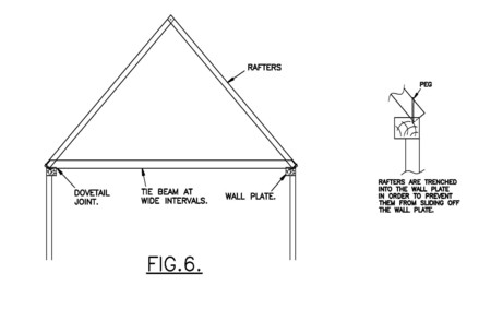
These joints can deteriorate after hundreds of years of service and they are often found supplemented by blacksmith made iron cramps fitted to the tie beam and wall plate by large iron staples.
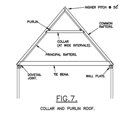
In practice, in order to reduce the size of the rafters, purlins (timbers running along the length of the roof) were added to support the rafters at mid span and these were in turn supported by larger principal rafters joined by collars at intervals of usually about 2-3 metres (see Fig. 7). This is a very common arrangement and could be thought of as the classic timber framed roof type. In respect of preventing spread of the walls the arrangement is exactly the same as the one in Fig. 6. This arrangement works well but the tie beams can get in the way and they are often cut or removed during modifications to buildings without other means of resisting the spread being provided. This can lead to severe outward movement of the walls, which can often be seen around Suffolk.
Another traditional and very early arrangement is the crown post roof (Fig. 8) which can be thought of as a combination arrangement. In the upper section of the roof the rafters are tied together by the high level collars in the same way as Fig. 5 but in this case the collars are in turn supported by the crown plate which holds up the centre of the roof structure in the same way as a ridge beam (see Fig. 4) but at a lower level. Normally the crown plate is a lot smaller than the size one would expect if the forces required to hold up the ridge of the roof are calculated. This is because large wall plates act as horizontal beams as in Fig. 5 providing some restraining force to support the rafters, and being themselves held in place by tie beams at intervals. The tie beams also act as support for the crown posts which support the crown plate. This form of roof construction was gradually superseded by the collar and purlin type (see Fig.7) before 1600.
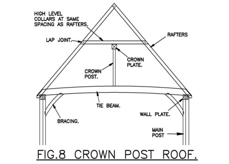
It is interesting that as the collar and purlin roof came to the fore and wall plates were called on to resist more horizontal thrust, the standard wall plate splice detail gradually changed from one with a horizontal splice to a vertical splice which was better able to resist the horizontal thrust.
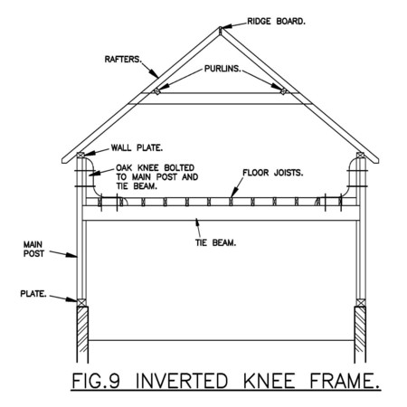
Two other variations on the collar & purlin roof allow the wall plate arrangement to be used where tie beams would compromise the inhabited space. The inverted knee frame is often used in granaries where there is little wall height above floor level; large timber knees which are connected to timber cross beams at intervals hold the wall plates in section (see Fig. 9), acting together with the cross beams as a U shaped frames.
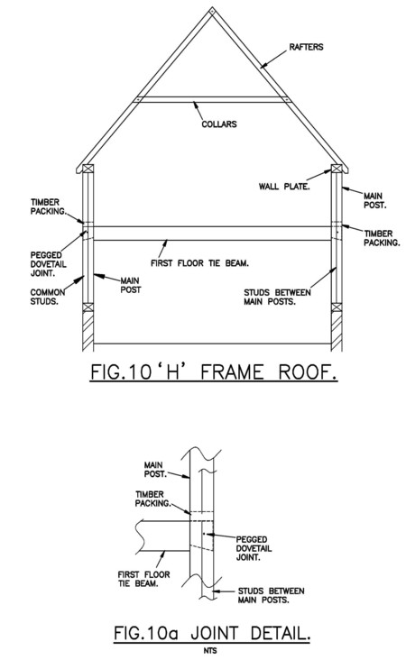
The other variation is the H frame roof often used in 17th Century cottages and often associated with somewhat low grade timber size and quality. Here large main posts run from the plinth walls up to the wall plates and these are held together at first floor level by cross beams with a dovetail tenon joint (see Fig. 10 & 10a).
With any of these arrangements the amount of spread force the roof structure will be called on to resist is directly proportional to the weight of the roof, so replacing a corrugated iron or asbestos roof with pantiles can lead to spread of a roof that was previously satisfactory.
In one house we have recently inspected one of the main posts of an H frame roof had been simply removed, leading to severe roof spread, and various attempts at strengthening the wall plate subsequently had not addressed the root of the problem.
Having said all this, timber framed structures do act in a more holistic manner than I have suggested in this article, and there are many more subtle variations on what has been described.
The problem of resisting roof spread is a real one, and it is always worth checking how roof spread is resisted when carrying out repairs or modifications to a timber framed structure. This will ensure that any repairs or modifications undertaken will not harm the existing structure. Knowledge of how roof spread is resisted can also allow you to look at timber frame roof structures in a new light.